What
is a "Command File"?
MillWrite is capable of reading a "command
file", which is a list of
instructions on what to do. This enables you to
use MillWrite on in an automatic or
semi-automatic mode.
If you download and install MillWrite,
(or this
version partially translated into German),
you can download and run this sample command file:
MillWrite-command-file,-cut-triangles-and-engrave.m8c
For two examples of how you can use
this feature:
1) Automatic CNC production
If you have software in your shop that is
creating part numbers, and if you need to engrave those part numbers,
then that software could create a MillWrite command file
that specifies the part number. The software would then call MillWrite
with that command file. MillWrite would follow the instructions in that
command file, and create a CNC program to engrave that particular part
number. This enables you to create CNC programs without any human
intervention.
2) Semi-Automatic CNC production
If you find that you are repeatedly doing the
same operations over and over, with only a few changes between them,
you could create a software program that asks you for the information
on how to make the particular part, or what to engrave on the part, and
after you have specified those parameters, your software creates a
command file for MillWrite.
Your
software could then call MillWrite to run that command file,
and MillWrite could either leave the job on the screen for you to
verify and/or modify, or it could create a CNC program for you.
For example, if you are repeatedly drilling some holes in
parts that you are making, but occasionally you have to modify the
quantity and/or placement of the holes, you would create a
software program that lets you specify the quantity and/or locations
for the holes, and after you have specified the information, your
software would create a command file for MillWrite that specifies those
particular holes to be drilled. This would be easier and more foolproof
than create a drilling program yourself for every part.
How to run a command
file
There
are several ways to run command files. Normally you would want to call
MillWrite from another software program. This method allows MillWrite
to be used automatically by other software.
If you are
creating your own software, you can call MillWrite from that software
with the name of the command file. For example, in the C language,
you would call it like this:
char MillWrite_8_folder[]
= "C:\\MillWrite_8\\"; //
folder that has MillWrite_8.exe
char MillWriteCommandFilename[200];
strcpy (MillWriteCommandFilename, "engrave text command file.m8c");
ShellExecute( NULL,
"open", // Operation to perform
"MillWrite_8.exe",
MillWriteCommandFilename,
MillWrite_8_folder,
SW_SHOW);
However, when you are designing and testing your command files, these
two methods are the most useful:
• Drag and drop a command file on top of the
MillWrite icon.
•
At the Drawing page, set one of the User-Defined Buttons to run
a command file. Then, when you click that button, it will ask you
to
select the command file, and when you do, it will run it for you.
If you want the help file for the User Buttons, download all of the
help files from this
page.
Command
files have three
possible outputs:
1) Create a CNC file that is saved on
the hard disk. MillWrite exits when finished.
2) Create a CNC file that is transmitted via serial port to
the CNC controller. MillWrite exits when finished.
3) Create a job file that remains on the computer screen
for you to deal with. MillWrite remains active so that you
can see the job file and decide what you want to do with it.
Command
files can modify
existing jobs or create new
jobs
1) Modify an existing job.
A command file can modify a job that you have
previously created and tested. This is useful when you want to do the
same job over and over, but each time you want to make some slight
change to it. For example, you might want to engrave a particular part
over and over, but each time you need to change one or move of the text
items, but you do not want to change any of the text locations, tool
feed rates, or anything else. In that case, you would use the "open
job=" command to open that particular job, and then modify only the
items that you want to change.
This is the easiest and most foolproof way of using a command file
because you can test the job ahead of time to make sure that you have
set everything correctly in regards to the tool's feed rate, the text
height, the tools' cutting depth, etc..
Your CNC program will be perfect when you make subtle changes to a job
that you have already proven to work correctly.
2) Create a new job.
A command file can create polylines, text to
engrave, data matrix barcodes, and other items, so you could create
whatever you need. MillWrite will give each new item whatever defaults
you have set in MillWrite, and you can override any of those defaults
with the command file, if you need to.
If your default feed rate, tool number, text type, and other parameters
have been set appropriately, then this is an easy way to create
programs to engrave some tax, or to cut a logo.
Structure of the command file
• The command file is a plain text
file
that lists the commands one after the other.
• The commands are processed
in the order that they are listed, just like a human follows a list of
instructions.
• The commands can use upper and/or lower case.
• There are two types of commands:
1) Commands that have
an equal sign.
These commands set a value. The value
follows
the equal sign. For example, the following command will set the radius
to 1.34 units:
radius=
1.34
The following command will open the job with the filename of "Engrave
serial number.job"
open job= Engrave serial number
2) Commands without
equal signs.
These commands do something, but they don't
set values. For example, the following command duplicates the texture
geometry that is active:
duplicate
• Use ASCII 135 to separate lines of text, ie, ‡
The phrase "ASCII 135" represents the ASCII
character #135, which is one of the characters that people used to make
footnotes. It looks like this: ‡
Each command has to fit on one line. As with a typical CNC program, the
invisible carriage return and linefeed characters are used to separate
the commands from one another. If you want to engrave a paragraph, all
of the text has to be on one line, and the way to do that is to
separate each block of text in the paragraph with the ASCII character
135 to show MillWrite where a block of text ends. For example, to
engrave these three lines:
Part 5501-a
SN: 123
Made in USA
Put that footnote character at the end of each line like this:
engrave=
Part 5501-a‡SN: 123‡Made in USA
You don't need to put a footnote character at the very end of the
text.
The list of commands
Here are the commands that MillWrite has right
now.
• *
The * is a comment for yourself, MillWrite ignores it
Don't put a comment on a line that has text or MillWrite will assume
it's part of the text.
It is best to put
the comment on a line by itself.
• countersink depth=
• countersink num=
• duplicate
•
engrave=
use ASCII 135 to
identify the end of each line of text
• feed=
• line length=
•
polyline
followed by x, and y values, and optional z, values
• machining batch=
• machining order=
• max depth per cut=
• move to xy=
• open job=
• radius=
• replace
text=
use ASCII 135 to identify the end of each line of text
• rotate=
• scale xyz=
• speed=
• surface
radius=
the radius of the cyclinder , which may be on a 4th axis
• surface
z=
• tap depth=
• tap num=
• text
align=
• text angle=
• text height=
• text length=
• text height and length=
• tool depth=
• tool diameter=
• tool num=
• tool z surface=
• use
item=
followed by the text name of the item
to activate
• work
offset=
eg, G54, G55, etc
• x=
• y=
• edit group
for editing a
"grouping"
• finished with group
• save cnc=
• transmit cnc=
• apply tool table
• disable 4th
• read tool text
file=
ie, get tools from tool list.txt
• remove unused
•
reorder
reorder machining order to reduce rapid
moves
• make
datamatrix=
creates a Data Matrix barcode
• cell size=
only for Data Matrix barcodes
Concepts behind the command file
Some commands need to be placed in a certain
order in order for them to work properly, but some commands can be
placed anywhere because they are merely instructions to MillWrite. For
example, the command to save the CNC file ("save cnc=") can be placed
anywhere because it is simply telling MillWrite that you want the CNC
program saved on disk. Example:
save cnc= c:\NC Programs\engrave part number.cnc
That command does not modify anything, so it doesn't matter where in
the command file you tell MillWrite that you want the CNC program saved.
However, some commands modify geometry or text, and that requires that
they be placed after the text or geometry has been made "active". If
you are creating new text and geometry, an item becomes active as soon
as you create it, and it remains active until you create some other
item.
For example, the command to create some text is "engrave=". After the
text has been created, you can use any of the text or tool modification
commands to adjust that text. It doesn't matter what order those other
commands are in because all of them operate on the active tax. Both of
the following sets of commands will do exactly the same thing:
engrave= Part # 12-44
revB this creates the text and
makes it active
text height=
.25
it doesn't matter what order these other commands are in,
tool depth=
0.034
as long as they are after the "engrave=" command
tool num= 4
engrave= Part # 12-44 revB
tool depth= 0.034
tool num= 4
text height= .25
Need a Command that does not yet exist?
MillWrite has the ability to process the
commands that
people have requested, but there are hundreds of possible commands that
MillWrite could process. Therefore, if you need a particular feature,
add for it, and it will be add it to command list, assuming it is
practical to do so.
A description of the commands
Note that after the
= you can put one or more blank spaces to make
it easier to read.
• open job=
This command will open a
job and allow you to make modifications to it. Although it should be
obvious, this should be one of the very first commands in the command
file because in order to modify an existing job, you must first open it.
• You do not need to include
the extension ".job".
• If you do not include a
drive and folder, MillWrite will use whatever drive and folder that you
specified to be the default folder for for job
files (you set that at the Setup page).
• use item=
You need to use this command when you want to open
an existing job and modify one of the items within it.
A
text item is identified by its text, and rectangles, polylines, and
other items are identified by the "name" that you have given the item.
In case you have not noticed, most of the items that you create have a
"name" data field that is you have probably left blank. If you want to
modify any of those items with a command file, you must give that item
a unique name.
For an example of how to use this command, assume
you created a job file that engraves a part number, serial number, and
recycling symbol, and assume that you want to change the serial number
each time. In that case, you might set up the serial number as "serial
number", or as "replace this text". You could modify that serial number
simply by making it active with the following command:
use item= serial number
replace text= SN 0034-3
Or:
use item= replace this text
replace text= SN 0034-3
Note:
you don't have to specify the complete text, or the complete name, of
the item. You only have to enter as much text as is unique. For
example, assume you have these two lines of text in your job
file:
replace
this text to engrave part number
replace this text for
serial number
You can make the first text item active with any of the following four
commands:
use
item= replace this text to engrave part number
use item= replace this text to engrave part
use item= replace this text to engrave
use item= replace this text to
And you can make the second text item active with any of these three
commands:
use
item= replace this text for serial number
use item= replace this text for serial
use item= replace this text for
• replace text=
Normally
you use this command to replace the text that you want to engrave. It
will also change the name of a polyline, rectangle, or other item, if
you want to do something more complicated (an example of a more
complicated use will be mentioned farther down in this document).
Note:
each command can be only one line long. Therefore, if you want to
replace a text item with multiple lines of text, you need to separate
each line of text with an ASCII 135 character to let MillWrite
know that each
where to put the line breaks. For example, assume that you want to
replace the text to engrave with the following paragraph:
Do not put in dishwasher.
Do not immerse.
Part number 355-3
Made in USA.
Use the ASCII character 135 to separate the lines, like this:
replace
text= Do not put in dishwasher.‡Do not immerse.‡Part number 355-3‡Made
in USA.
• x=
This will change only the X coordinate of the
active item. Example:
x=
3.456
• y=
This will change only the Y coordinate of the
active item.
• move to xy=
This
will set both the X and Y coordinates of the active item with just one
commmand. Separate the X and Y values with a comma, tab, or a blank
space. Example:
move
to xy= 3.456, -7.654
• text height=
This will set the height of the active text.
See the blue
note below.
• text length=
This will set the length of the active text.
See the blue
note below.
• text height and length=
This
will set both the height and length of the text and adjust the width
ratio so that the text fits that particular height and
length.
Note about setting
the text height and length:
Text
has a height, length, and with ratio. You can set only two of those
three parameters because the third is calculated from the other two.
If
you are creating new text, it will be given a width ratio of 1.0. If
you set the height of the text, the length will be adjusted in order to
keep the width ratio at 1.0. If you set the length, then the height
will be adjusted. If you want to set both height and length, then use
the "text height and length= command.
However, if you are
modifying a text item in an existing job file, and if the existing text
already has a width ratio other than 1.0, then if you use the "text
height= or "text length= commands, MillWrite will assume that you are
trying to force the text to be a certain height and length, and so it
will allow the width ratio to change.
To summarize this, when
you create a job file that you plan to modify with a command list, and
when you want to modify the text items in that job file, set their
width ratio to 1.0 if you want the width ratio to remain 1.0 after you
have modified them. If you modify a text item that has a width ratio
other than 1.0, MillWrite will assume you are trying to force the text
to fit a certain whatever height and length that you designed for that
particular text item.
If you want the text to fit a certain
height and length, The best option would probably be to use
the command: "text
height and length="
• text angle=
This
will set the rotation angle of the text. Enter a value in degrees. The
3 o'clock position is at 0°, and the 12 o'clock position is at 90°.
• text align=
If
you want to set the alignment for the text, specify a value from 1 to
9. MillWrite offers nine alignment points for text. The XY coordinates
of the text refer to the alignment point. For example, the following
commands set the upper left corner of the text to be at a coordinate of
4.5, 7.3:
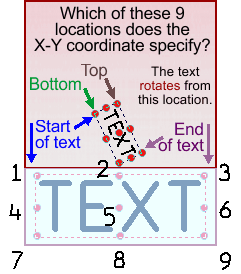
use item= replace this text
replace text= Part #: 56900 -rev2
text height= .25
text align= 1
move to xy= 4.5, 7.3
• feed=
This will set the feed rate of the tool for the
active item.
• speed=
This will set the speed of the tool in RPM for
the active item.
• tool depth=
This
specifies the depth for the tool for the active item. The value is
always positive. For example, the following command will set the tool
to a depth of 0.5 units below whatever the surface is.
tool depth= 0.5
• tool diameter=
This sets the tool diameter of the active item.
When
you are engraving geometry, you do not need to specify the tool
diameter because it has no effect on the CNC program. However, when you
are contouring or pocketing geometry, the tool diameter is critical.
Also, when MillWrite engraves text, it separates the characters by the
width of the tool so that they don't cut into one another.
• tool num=
This will specify the tool number for the
active item. This will become the "T" number in the CNC program.
• tool z surface=
This
sets the Z coordinate at which the tool would touch the surface for the
active geometry. It sets the data field that MillWrite refers to as "Z
Surface"
• max depth per cut=
This will set the max depth per cut of the tool
for the active item.
• machining batch=
This will set the machining batch of the active
item.
• machining order=
This will set the machining order of the active
item.
• duplicate
This
command will duplicate, that is, make a copy, of whatever item is
active. This command is useful when you need to engrave or cut several,
nearly-identical items. You only have to create one item, and then you
can duplicate that one item, and make changes to it.
For
example, assume you need to engrave text at various openings on a mold.
Some molds have to be engraved at five different locations, and others
have to be engraved at six locations, and others need to be engraved at
eight locations. You could create a job file for every possible
situation, but if you have dozens of possible situations, that would be
a lot of work.
It would be easier to create just one text file
with just one text item. You would then activate that one text item,
put it into the proper XY location, and then duplicate it for the
second location. You would then change its XY coordinates, its text,
and whatever else is necessary, and then you could duplicate it again.
The
following set of commands will modify the text item that is called
"replace this text". It will change that text to "Main Power", and then
duplicate that item. The duplicate item will be moved to an XY
coordinate of 1.23, 4.5, and the text will be replaced with ON/OFF.
Then that text item will be duplicated, and the x-coordinate will
remain what it already is, but the Y will be changed to 7.44, and the
text will be replaced with "Fuel Level".
use
item= replace this text
replace text= Main Power
duplicate
replace text= ON/OFF
move to xy= 1.23, 4.5
duplicate
y= 7.44
replace text= Fuel Level
• rotate=
This
will rotate the active item by whatever degrees number of degrees you
specify. The rotation is anti-clockwise if the value is positive, and
clockwise if you enter a negative value. For example, the following
command will rotate the item by 20° anti-clockwise.
rotate=
20
When
engraving text, you do not need to use this command. Text has a special
command, "text angle=, which lets you specify the rotation angle of the
text.
• scale xyz=
This will scale the active item by the X, Y,
and Z values that you specify.
When
you are engraving text, you normally will not want to use the scale
command because you can more easily control the size of the text by
setting the text height, and/or the text length. However, when the text
is wrapped around a circular arc, or following a polyline, you might
want to use the scale command.
Normally you will not want to
scale in the Z axis, so you mormally would enter only one or two
values, or specify a Z scaling factor of zero. If the scaling factor in
Y is the same as in X, which is usually what you want to do, then you
only need to enter one value. For example, the following command will
scale the active item by a factor of three.
scale xyz= 3
That is equivalent to this command:
scale xyz= 3, 3, 0
If
you specify an X scaling factor that is different from the Y scaling
factor, then the item will be stretched or compressed. For example, the
following command will stretch the item 3 times in the x-axis, but only
two times in the Y axis.
scale xyz= 3, 2
If
you wonder why somebody would want to scale an item differently in X
and Y, one purpose is to make rectangles. For example, you could create
a job file that has a square that is one unit in size. Then, whenever
you want to cut a rectangle, the scaling factor becomes the size of the
rectangle. For example, if you want to cut a rectangle that is 5 units
in X and 7.6 units in Y, you would enter:
use item= 1 unit square
move to xy= 1.23, 4.5
scale xyz= 5, 7.6
If
you are scaling a circle, the scaling occurs from the center of the
circle. If you are scaling something else, it occurs from wherever the
start node is. Likewise, when you use the "move to xy= command, if you
are moving a circle, it moves from its center, otherwise it moves from
its start node.
• engrave=
If you want to create
a new text item, rather than use some existing text, then use this
command. As with the "replace= command, if you want to create a text
item with multiple lines, separate them with ASCII 135. For example,
the following command creates one text item with two lines of text:
engrave= This is new text.‡And this is the 2nd line.
• polyline
If
you want to create a polyline, use this command, and follow it with a
set of XYZ coordinates. This is the only command that does not follow
the rule that each command is on its own line. In this case, the
command polyline is on its own line, but underneath it are sets of
coordinates, one for each node of the polyline. For example, the
following command list will create a triangle:
polyline
0,0
6,0
3,5
0,0
The
start node of the polyline is the first XY coordinate, which in this
case is 0,0. If you do not specify Z values, they will be set to zero.
This command can be useful if you need to engrave some lines,
arrowheads, or other shapes.
If you specify Z values, you will create a 3D polyline, which will
enable you to cut 3-D shapes.
After you create a polyline, you can duplicate it, move it, scale it,
or rotate it.
• line length=
A
polyline can be a long chain of lines, arcs, and splines. If you create
a polyline that is
just one, single line, then you can use
the "line
length= command to set the length of that line. For example, you could
create a horizontal line in a drawing, and refer to it as "horizontal
line". Your command file could then set it to whatever length you want,
and move it into whatever XY location you please. For example, the
following command list will set it to a length of 5.6 units, and move
it to 1.23, 4.5.
use item= horizontal line
move to xy= 1.23, 4.5
line length=5.6
• radius=
This
sets the radius of a point or circle. If you are going to create CNC
code, you do not need to set the radius of a point. However, if you are
using the command file to create a job file that remains on the
computer screen, then you might to give the points the radius of the
drill so that you can by see their size.
use item= contoured circle
move to xy= 1.23, 4.5
radius=6.9
• surface radius=
When you are cutting a cylinder on a 4th axis,
or a cylinder that is clamped into a vise, this sets the radius of that
cylinder.
• surface z=
When
specifying a cylinder, or other three-dimensional shape, which you
normally do at the SETUP page, this is the Z coordinate at which the
tool would touch the top of the 3-D shape.
Note: do not get
command this mixed up with the "tool Z surface=. The "Surface z=
command defines the block of material that you are cutting, which
affects the entire job, whereas "tool Z surface= sets the tool for only
one piece of geometry.
There will be only one "surface z=
commands in a command file, but there may be as many "tool Z surface=
commands as there are items to cut.
• make datamatrix=
If you want to cut a data matrix barcode, this
command sets the data for the barcode.
Examples:
1) To cut a data matrix barcode that contains the
data "Part # 123786", do this:
make datamatrix=
Part # 123786
2) To cut a data matrix barcode that contains
these 3 lines of data:
Part
# 123786"
SN 43304-1"
Made in USA"
Use the footnote character ASCII 135
(‡) to show where you want a line break, like this:
make datamatrix= Part # 123786‡SN 43304-1‡Made in USA
• cell size=
This
command is valid only if you have made a data
matrix barcode active,
either by creating it with "make datamatrix=, or by selecting one from
an existing job. This sets the distance between the cells of the
barcode.
• read tool text file=
If
you have used MillWrite to create a plain text file of your tools, this
command will read one of those lists into the tool table.
For example, this will set your tools to whatever is in the file
"Engrave brass tools.txt"
read tool text file= Engrave brass tools.txt
To
create a plain text file of your tools, switch to the Setup page of
MillWrite, and then click your RIGHT mouse button over the tool list
button. A menu will appear, and one of the options is to Write The Tool
List To A Text File. If you use that feature, you can save one or more
tool lists, and you can modify them, also. The "read tool text file=
command will read whichever of those tool lists you specify after the
equal sign.
• apply tool table
This command will apply your default tool table
to the items in the drawing.
Be
careful about where you place the "apply tool table" command in the
command file. That command applies the tool table immediately, so it
affects only the items that have already been created, not the items
that are created after this command.
If you use the "open job=
command to modify an existing job file, then it would be useless to put
the "apply tool table" before the "open job= command. Instead, place it
afterwards so that after the job has been opened, the tool table is
applied to everything in the job. You can then use the command file to
modify whatever tool settings you want to change.
For example,
the following commands will open an existing job called Engrave part
number, and the next command will read Engrave brass tools.txt to
create a tool list, and then that tool list will be applied to
everything in the job. After the tool table has been applied, the tool
depth for the engraved text called "replace this text" is overridden
with a new value.
open
job= Engrave part number
read tool text file= Engrave brass tools.txt
apply tool table
use item= replace this text
tool depth= 0.034
replace text= Part #: 56900 -rev2
text height= .25
text align= 1
move to xy= 4.5, 7.3
If
you put the "apply tool table" command at the end of the command list,
then you can ensure that all of the items in the drawing have those
default tools settings.
If you are creating a new job there is
no sense in putting this command at the beginning of the command list
because there will be nothing in the job file yet. In that case, you
would put it at the end of the command list so that it sets everything
that you create to the default tool settings.
The following commands can be placed anywhere in the
command file because they affect the entire job, not any individual
item:
• reorder
This command tells MillWrite to set the cutting
order of the items in the job to reduce rapid moves.
• remove unused
This
command has an effect only when you are modifying an existing job. It
does nothing when the command file is creating a new job.
When
you modify an existing job file, there might be some situations in
which you do not want all of the text in that job file to be engraved,
or you do not want all of the drilling points to be drilled, or you do
not want all of the geometry to be contoured, etc.. Rather than delete
the items that you do not want to use, you can use this command, and it
will delete everything that you have not made active.
For
example, assume you have a job file that has a line of text to engrave,
a logo to engrave, and a drilling point. The following command list
will engrave the text, but delete the logo and the drilling point:
save cnc= 1000.EIA
remove unused
open job= Engrave serial number
use item= replace this text
replace text= SN 0034-3
If you want to use the drilling point, then you
have to make it active, even if you don't do anything to modify it. For
example:
save cnc= 1000.EIA
remove unused
open job= Engrave serial number
use item= replace this text
replace text= SN 0034-3
use item= drill hole
• transmit cnc=
If
you specify this command, instead of saving the CNC program on disk,
MillWrite will transmit the CNC program through the serial port to the
CNC machine. This command is useful only when your computer is
connected to the CNC machine through a serial port, and the machine is
ready to receive.
MillWrite will use whatever serial port
protocol you have specified in this command. For example, if you have
two serial port protocols, one of them is referred to as "Centroid on
COM1", then the following command will use that serial port
specification to transmit the file:
transmit cnc= Centroid on COM1
• work offset=
If
you want to specify the work offset number, and G54 to G59, enter the
value in this command. For example, if you want G56, use this command:
work offset= 56
Note
that you will not get the G54 to G59 command in the CNC program unless
you specified that the postprocessor include a work offset number. To
do that, you need to put a "W#" in the Starting Code block and/or the
Tool Change block, of the postprocessor.
• disable 4th
When using a 4th axis, this command will cut
whatever is
the active item by holding the 4th axis motionless, rather than by
rotating the 4th axis.
This is the same as checking the box that
says "Disable 4th axis for this item", which you find at the bottom of
the Tool tab, it the data field called "More options".
|
